• Visit https://www.embeddedcomputers.net/ for Hardware; Software and all other things related to FlashcatUSB

HELP - Connecting PCB 2.1 to SB6182 SPI

Ramdog

New Member
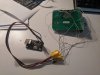
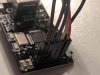
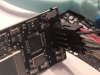
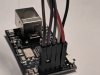
Well I soldered on the connections as per instructions in the manual. I get both lights on and FlashcatUSB status: Connected; Device mode: Serial Programming Interface (SPI). However, Flash memory not detected on SPI NOR Mode. If I change the mode to Quad Flash I get "Flash memory detected but not found in Flash Library"

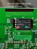
Is this PCB board not compatible any longer, or do I need to connect more wires to the SPI on the SB6182?
 

Attachments

  • IMG_20180716_182524.jpg
    IMG_20180716_182524.jpg
    137.1 KB · Views: 38
  • 25L032 Pinout.jpg
    25L032 Pinout.jpg
    189.4 KB · Views: 40
Can you show the complete connection from the PCB to FCUSB ?
 
Hi D3m0n,

I really appreciate the response. I think its been 15 years since you last helped me with an SB5101. Anyway, attach are the best I can do with pictures taken of my setup with an included diagram for each pin color and destination (if it makes sense). Not my best soldering but each contact has continuity through the cable.

Thanks again for any help you can provide.IMG_20190518_160759.jpg
 

Attachments

  • Diagram SB6182 to Flashcat USB PCB 2.1.pdf
    64.2 KB · Views: 11
  • IMG_20190518_153305.jpg
    IMG_20190518_153305.jpg
    3.2 MB · Views: 39
  • IMG_20190518_153355.jpg
    IMG_20190518_153355.jpg
    1.7 MB · Views: 33
  • IMG_20190518_153414.jpg
    IMG_20190518_153414.jpg
    1.7 MB · Views: 34
  • IMG_20190518_153507.jpg
    IMG_20190518_153507.jpg
    1.8 MB · Views: 40
Sine you have v2.1 instead of connecting VCC to the flashcat, connect this instead to a 3.3v power source like a usb-ttl (also make sure you connect the grounds)

Reason being is 2.1 and earlier are not that great for providing VCC voltage to in circuit SPI chips (that are still soldered to the board,) they only work fine when they are desoldered.

WP_20180224_15_05_49_Pro - Copy.jpgWP_20180224_15_06_09_Pro - Copy.jpgWP_20180224_15_06_17_Pro - Copy.jpg
 
Good evening Folks,

I just connected a 3.3v source and ground from a USB directly to SB6182...….no change in connection. "
Flash memory not detected on SPI NOR Mode" is still the outcome.

Thanks ricktendo…….gave it a shot, maybe D3m0n has another thing to try?

Thanks again folks!
 
Do I need to connect WP# and/or HOLD# to the FlashCatUSB to read the flash on SB6182?

Thanks
 
you have very long cables that measure 20 cm in total as max, the other uses flux amtech not clean of the most economical, your work is horrible! you will end up ruining the solder in the wson ... finally you can try doing short by joining the transistor below the processor.

I leave screenshot for you to identify it you should detect it without using external vcc and use vcc feed with 3.3v also the #hold pin


https://gyazo.com/296cd30c1f4be859aac903c2ef9d7d57
 
And get yourself some better solid core wire, like "kynar" or "wrapping wire". This will make it really easy and less destructive to solder to the solder points.
 
Thank you arrobazo and ricktendo. I will connect the #Hold pin and use better solder. Also try joining the resistor below the processor.

Really appreciate the feedback!
 
Last night as I was going through all my connections I decided to see if the modem was still functional. I connected the modem to its power source and all I got was a brief flash of all lights and then silence. Now I know why I can't read the SPI Flash......this modem is bricked! I will be further testing to see how to Debrick this little guy. Thank you folks for all the help and feedback.
 
Make sure you disconnect from the FCUSB because this may prevent your modem from booting. Also you should not have any problems detecting the flash of a modem that is soft-brick.
 
Hi Ricktendo,

Yeah.....it was disconnected from FCUSB. My knar wiring is coming in tomorrow so I am hoping I can connect to the SPI on this modem. If not, would make a fine door stop.:)
 
Back
Top