• Visit https://www.embeddedcomputers.net/ for Hardware; Software and all other things related to FlashcatUSB

Request/Help: SB5102 SPI pinout

flyspell

New Member
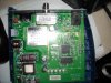
This device has a BCM3349 CPU and should be identical to the SB5101 except for the Flash size which I think it's around 8MB on this device. I've been searching information regarding this device without much luck. There's a "tutorial" on the usbjtag nt website but it doesn't explain much for a non-expert user.

Here's the link just in case: http://usbjtag.com/jtagnt/sb5102.php

I currently have the PCB v1.2 (pretty old) and loaded the SPI (v3.04) firmware on it. However, I haven't been able to get a connection with the device.

I then compared the above link, with the SPI Pinout on this link http://www.blackcatusb.net/threads/blackcatusb-ejtag-spi-pinouts.11/ without any luck either.

I'd be glad to know how it should be connected.

PS: I guess the 5101U script should work well with this device so that shouldn't be a problem as soon as I establish a connection.
 
This is how the modem looks like. This particular model is blue.
5L95I15Ha3E83M93N6c7d65b8c850b4e915fb.jpg
 
It seems like I have established connection, however, I get an SPI NOT SUPPORTED message :(
24bm5jp.jpg


Could it be that I'm still missing something (or did something wrong) or this SPI (spansion FL016A1F) is not supported ?
 
How are you connecting your device , direct to the SPI chip or as in the NT tutorial ?
If you are connecting as per the NT tutorial , try reversing your SI and SO connections and see what output you are getting. Also the ISP connection would goto the VCC connection on your BCUSB.

That specific chip is supported , so it is a matter of getting your connection right.
 
I'm connecting the device as in the NT tutorial. if I reverse the SI and SO connections I get no output, or unable to detect the device. As per ISP connection I did connect it to the VCC from the BCUSB.

Test #1
VCC from BCUSB goes to ISP on modem
SI on BCUSB goes to SO on modem
SO on BCUSB goes to SI on modem
Result: Connected to FLASH (JEDEC: 80 810A) but says device is not supported

Test #2
VCC from BCUSB goes to ISP on modem
SI on BCUSB goes to SI on modem
SO on BCUSB goes to SO on modem
Result: Unable to connect to compatible device

* Tests are done with the device both unpluged first then again plugged in to the wall electricity.

Any other clues or suggestion?
 
Ok so keep your connection as per Test #1.
Now when you get that on the console tab , if you press detect (F1) does it keep on coming up with the same JEDEC ID ?
 
I'm still struggling with this.
I must have corrupted the flash by now, since the modem won't boot after powered on. If I'm still lucky the (SIP) IC is still not damaged.

So, this were the steps I followed (without desoldering the SPI IC from the modem), without any result:
  1. I carefully checked the datasheet of the Spansion S25FL016A.
  2. Triple checked the pins for continuity (GND on SPI/modem goes to GND on BCUSB, CS on SPI IC goes to CS pin on BCUSB, etc.)
  3. Soldered a cable directly to the SO pin on the SPI IC/modem because I wasn't getting 1:1 continuity on the J303.
  4. Connected the SO already-soldered cable to the SO pin from the SPI IC to the SI pin on the BCUSB. Then tried SO to SO and SI to SI directly.
  5. First connected the VCC pin from the SPI IC (which was PIN 1 on J303) to the VCC on the BCUSB.
  6. Decided to solder a cable directly from the VCC pin on the SPI IC and connected it directly to the VCC pin on the BCUSB.
  7. Unplugged and plugged back in the BCUSB USB cable without any power source on the modem. No luck... Flash detected but JEDEC 000000 <----
  8. Same as above but now with power source connected to the modem.. No luck, couldn't detect anything. No flash nothing.
I will get JEDEC 000000 everytime now.

So, my questions are:
What could I be possibly doing wrong?
Did I fry the SPI ?
Can I still program the chip even tho the modem wont boot now?
What am I missing? How should all this be done?
Are PROG and RST pins still there? I don't see them anymore on latests SPI Firmware pictures.

* star indicates the first pin on the SPI IC

1. CS *
2. SO
3. W
4. GND
5. SI
6. SCK
7. HOLD
8. VCC

PS: The SB5102 revision shown on the picture from the NT website (posted a few POSTS above) is not the same revision I have. Just in case, my SB5102 is revision 3.
Also, keep in mind that I have just two cables directly soldered to the SPI IC.
 
Ok if nothing has been flashed to the Chip there is no way of corrupting it ,,, hopefully you have not damaged the board by connecting to different pin outs.

Lets try bypassing the pin outs on the board completely and connect directly to the chip itself , for the VCC pin on the chip do not connect to the BCUSB try use an external power source ( cut up USB lead) to add power to that.
 
Ok. I finally got it by connecting an external power source (USB lead +5V) directly to the VCC pin on the chip. Then ISP pin from the board goes to VCC on the BCUSB and Voilá!

The only pin out I bypassed from the board was the SO pin, I soldered it directly to the chip.

I could then detect the SPI chip, it loaded the SPI flash... it looked good... however... apparently I shorted some pins from the SPI chip and it corrupted the data, somehow data got overwritten or something... I made a full flash backup and then individual backups (boot, firmware, cfg, etc.). The reason the modem was not "turning on" is because the data in memory/flash was corrupted, so no LIGHTS after powering on the modem.

I got a full backup from someone so I flashed it. It worked (modem booted fine), so I proceeded to compare, cfg images, boot images, etc.

Here is a picture:

10dfig7.jpg


Problem is, the bytes will never be the same. For example, at the beginning the 04 got changed to FF but further on a 3C got changed to FF and then a 03, etc. etc.

The pattern is the same however, FF xx xx xx FF (where xx are unchanged bytes).
However, I could just "TRY" to fix the CFG bin since is all I'm really interested and is only 64KB. but I'm not sure which software will let me search for "patterns" to I could try to replace corrupted bytes fast.

If you have ANY idea, suggestion or whatever, PLEASE let me know.
 
Are you talking about trying to repair your corrupted backup ?
Have you tried extracting the CFG area from your Corrupted backup and trying that , as it looks as if only your bootloader seems to be corrupted.
 
Are you talking about trying to repair your corrupted backup ?
Have you tried extracting the CFG area from your Corrupted backup and trying that , as it looks as if only your bootloader seems to be corrupted.
Yes, I'm talking about repairing corrupted areas.

Everything I extracted (CFG, BOOT, FIRMWAREs) is corrupted somewhere with the FF xx xx xx FF hex pattern. I would attach a picture of the CFG but it looks similar to the BOOT img in terms of "corruption".

You could easily notice how the image/backup is not completly damaged, but replacing (fixing) those bytes is the question.

I even tried flashing just the original (corrupted) CFG to the working flash backup (the one that boots fine), but I got a nasty message:
Serial Number dead01
HFC MAC Address 00:20:40:de:ad:01
 
Without knowing the bytes of your original CFG layout , you stand little chance of repairing it
 
i got one of those.. please a tutorial of diagrams with pictures for a proper connection to this device will be welcome.. i got SB5102 says rev. 3

i have blackcat usb with pcb 1.2 updated to latest firmware version.. i'm not very good with diagrams i need proper directions with pictures so i won't damage the modem.

My Best Regards
 
it's also a blue model (blue case) and firmware says: SB5102N-2.6.0.0-GA-00-NOSH

here is the pic of this particular model;/rev. inside:
 

Attachments

  • Picture 002.jpg
    Picture 002.jpg
    2 MB · Views: 30
is there any real example with real life picture or video + cable connected of this connection?

for some reasons i really can't risk to damage the original cfg area of this modem

My Best Regards
 
Sorry , but i do not have one of these devices , the diagram itself is straight forward though
 
Back
Top